Where Is the Logic Board on Iphone 6
Introduction
Follow the steps in this guide to replace the logic board in an iPhone 6s.
It's important to note that each iPhone's logic board and Touch ID fingerprint sensor are paired at the factory, so replacing the logic board will disable Touch ID unless you also install a replacement home button that has been properly paired to your new logic board.
You can also use this guide for reference to replace the logic board EMI shield stickers.
-
-
Before disassembling your iPhone, discharge the battery below 25%. A charged lithium-ion battery can catch fire and/or explode if accidentally punctured.
-
Power off your iPhone before beginning disassembly.
-
Remove the two 3.4 mm P2 Pentalobe screws on the bottom edge of the iPhone, next to the Lightning connector.
-
-
-
Optionally, apply mild heat to the lower edge of the iPhone using an iOpener or hair dryer for about a minute.
-
Heat softens the adhesive securing the display, making it easier to open.
-
-
-
Opening the display on the 6s separates a thin strip of adhesive around the perimeter of the display. If you prefer to replace the adhesive, have a set of new adhesive strips ready before you continue. It's possible to complete the repair without replacing the adhesive, and you probably won't notice any difference in functionality.
-
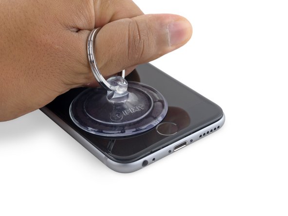
Apply a suction cup to the lower left corner of the display assembly.
-
Take care not to place the suction cup over the home button.
-
If your display is badly cracked, covering it with a layer of clear packing tape may allow the suction cup to adhere. Alternatively, very strong tape may be used instead of the suction cup. If all else fails, you can superglue the suction cup to the broken screen.
-
-
-
Pull up on the suction cup with firm, constant pressure to create a slight gap between the front panel and rear case.
-
Take your time and apply firm, constant force. The display assembly is a much tighter fit than most devices and is held down with adhesive.
-
Pulling too hard may damage the display assembly. Apply just enough pressure to create a small gap between the display assembly and the rear case.
-
If you have any trouble, heat the front of the iPhone using an iOpener, hair dryer, or heat gun until it's slightly too hot to touch. This will help soften the adhesive securing the edges of the display.
-
-
-
There is a notch on the underside of the display, just above the headphone jack. This is the safest place to begin prying the phone open.
-
Place the flat edge of a spudger into the gap between the screen and rear case, directly above the headphone jack.
-
-
-
Twist the spudger to widen the gap between the front panel assembly and the rest of the phone.
-
-
-
Insert the flat end of the spudger on the left side of the phone, between the display assembly and rear case.
-
Slide the spudger up the side of the phone to separate the adhesive and pop the clips free.
-
-
-
Remove the spudger and reinsert it on the bottom edge, where you pried the phone open.
-
Slide the spudger to the right, along the bottom edge of the phone.
-
-
-
Slide the spudger up the right side to continue separating the adhesive and popping the display clips free from the iPhone.
-
-
-
Use the suction cup to open the display, breaking the last of the adhesive.
-
Don't open the display more than 90º, as it is still connected at the top by three cables that may break if stretched.
-
-
-
Pull up on the nub on the top side of the suction cup to remove it from the front panel.
-
-
-
Gently grasp the display assembly and lift it up to open the phone, using the clips at the top of the front panel as a hinge.
-
Open the display to about a 90º angle, and lean it against something to keep it propped up while you're working on the phone.
-
Add a rubber band to keep the display securely in place while you work. This prevents undue strain on the display cables.
-
In a pinch, you can use an unopened canned beverage to hold the display.
-
-
-
Remove two Phillips screws securing the battery connector bracket, of the following lengths:
-
One 2.9 mm screw
-
One 2.2 mm screw
-
Throughout this repair, keep track of each screw and make sure it goes back exactly where it came from to avoid damaging your iPhone.
-
-
-
Remove the battery connector bracket from the iPhone.
-
-
-
Use the point of a spudger to disconnect the battery connector by prying it straight up from the logic board.
-
-
-
Push the battery connector away from the logic board until it stays separated from its socket, so as to avoid any accidental connection to the battery while you work.
-
-
-
Remove the following four Phillips screws securing the display cable bracket:
-
Three 1.2 mm screws
-
One 2.8 mm screw
-
-
-
Remove the display cable bracket.
-
-
-
Use a spudger or a clean fingernail to disconnect the front camera flex cable by prying it straight up from its socket on the logic board.
-
-
-
Disconnect the digitizer cable by prying it straight up from its socket on the logic board.
-
When reconnecting the digitizer cable, do not press the center of the connector. Press one end of the connector, then press the opposite end. Pressing in the center of the connector can bend the component and cause digitizer damage.
-
-
-
Make sure the battery is disconnected before you disconnect or reconnect the cable in this step.
-
Disconnect the display cable by prying it straight up from its socket on the logic board.
-
-
-
Remove the display assembly.
-
During reassembly, pause here if you wish to replace the adhesive around the edges of the display.
-
-
-
Use the flat end of a spudger to disconnect the rear camera from its socket on the logic board.
-
-
-
Remove the following two Phillips screws over the rear camera bracket:
-
One 1.6 mm screw
-
One 2.0 mm screw
-
-
-
Remove the camera bracket.
-
-
-
Insert a spudger to the side of the camera, between the rear case and the camera module.
-
Gently pry up on the camera to nudge it out from its housing.
-
-
-
Remove the camera.
-
-
-
Insert a SIM card eject tool or a paperclip into the small hole in the SIM card tray.
-
Press to eject the tray.
-
This may require a significant amount of force.
-
-
-
Remove the SIM Card tray assembly from the iPhone.
-
When reinserting the SIM card, ensure that it is in the proper orientation relative to the tray.
-
-
-
Remove the two 2.3 mm Phillips screws securing the upper component cable connector bracket.
-
-
-
Remove the upper component cable connector bracket.
-
-
-
Remove the following five Phillips screws securing the top left Wi-Fi antenna:
-
Two 1.5mm screws
-
One 2.3 mm screw
-
One 1.9 mm screw
-
One 2.0 mm screw
-
-
-
Remove the top left Wi-Fi antenna.
-
-
-
Use the flat end of a spudger to disconnect the audio control cable from its socket on the logic board.
-
-
-
Use the pointed tip of a spudger to disconnect the antenna cable from its socket on the upper right corner of the logic board.
-
-
-
Use the pointed tip of a spudger to disconnect the antenna cable from its socket on the lower left corner of the logic board.
-
-
-
Insert the flat end of a spudger underneath the Lightning connector ribbon cable. Lift up to disconnect it from its socket on the logic board.
-
-
-
Gently pull up on the antenna cable to de-route it from the two clips on the right side of the logic board.
-
-
-
Remove the 1.3 mm Phillips screw securing the NFC bracket to the logic board.
-
-
-
Remove the NFC bracket.
-
-
-
Remove the following two Phillips screws:
-
One 2.5 mm screw at the top of the logic board
-
One 1.4 mm screw set into the upper edge of the rear case
-
-
-
Remove the plastic clip.
-
-
-
Remove the final three screws securing the logic board to the rear case:
-
One 1.9 mm Phillips screw
-
One 2.5 mm hex nut
-
One 1.8 mm Phillips screw
-
-
-
Insert an opening pick below the lower edge of the logic board, between the board and the loudspeaker.
-
Use the opening pick to gently lift the logic board out of its housing.
-
Remove the logic board.
-


Conclusion
To reassemble your device, follow these instructions in reverse order.
Embed this guide
Choose a size and copy the code below to embed this guide as a small widget on your site / forum.
Preview
Where Is the Logic Board on Iphone 6
Source: https://www.ifixit.com/Guide/iPhone+6s+Logic+Board+Replacement/57073
0 Response to "Where Is the Logic Board on Iphone 6"
Post a Comment